Writing a “bare metal” operating system for Raspberry Pi 4 (Part 10)
Using multiple CPU cores
Instead of a background DMA transfer, I suggested that we might use a second CPU core to play the audio whilst our main core continues on. I also said it would be hard on the Raspberry Pi 4… and it is.
I wrote this code as I referenced Sergey Matyukevich’s work, for which I am very grateful. It did need some modification to ensure the secondary cores are woken up when the time is right. This code isn’t particularly “safe” yet, but it’s good enough to prove the concept in principle.
A note if you followed an earlier version of this tutorial
This part used to depend on adding kernel_old=1 to config.txt, which told the bootloader to load our kernel at address 0x00000 and start all four cores running it. Sadly, that directive is deprecated and newer firmware has broken it: the firmware now stages the image at 0x80000 as usual, but only relocates the first 512KB down to 0x00000. Our kernel is over 2MB (the audio is baked in!), so most of it never arrived - and the audio glitched at the exact moment playback crossed that boundary.
So we now do things the officially-supported way instead, and there’s good news: it’s the same “spin table” protocol that Linux itself uses to start the Pi 4’s cores. If you have kernel_old=1 or disable_commandline_tags=1 in your config.txt from before, remove them. Nothing beyond the usual arm_64bit=1 is needed, and our link.ld gets its old first line back, just like every other part:
. = 0x80000; /* Kernel load address for AArch64 */
How the Pi 4 really starts its cores
When the Pi 4 powers up, the firmware installs a small “stub” of code at address 0x00000 and points all four ARM cores at it. The stub sends the main core off to our kernel at 0x80000, but it parks cores 1-3 in a low-power loop, each watching its own 64-bit “release word” in a spin table:
- Core 1 watches address
0xe0 - Core 2 watches address
0xe8 - Core 3 watches address
0xf0
Each parked core sleeps on a wfe (Wait For Event) instruction. When it’s woken, it checks its release word and, if the word has gone non-zero, jumps to that address. So to run code on a secondary core, all we need to do is write an address into the right slot and execute a sev (Set Event) instruction to wake everybody up. That’s the whole protocol!
Booting the main core
Because only the main core enters our kernel now, the top of boot.S looks just like it did back in part9: we set the stack pointer to start below our code at 0x80000, clear the BSS, and jump to main().
A landing pad for the secondary cores
When the stub releases a secondary core, it arrives with no stack and no idea what we want from it. So we don’t point its release word straight at a C function - instead, we give every core the same assembly landing pad in boot.S, called secondary_entry:
secondary_entry:
    mrs     x1, mpidr_el1        // Check our processor ID
    and     x1, x1, #3

    ldr     x2, =__stack_start   // Get ourselves a fresh stack - location depends on CPU core asking
    lsl     x3, x1, #9           // Multiply core_number by 512
    add     x3, x2, x3           // Add to the address
    mov     sp, x3

    adr     x5, spin_cpu0        // Base watch address
1:  ldr     x4, [x5, x1, lsl #3] // Add (8 * core_number) to the base address and load what's there
    cbnz    x4, 2f               // If it's non-zero, go run it...
    wfe                          // ...otherwise sleep until the next event
    b       1b
2:  blr     x4                   // Run the code at the address in x4 (sets x30, so it can return to us)
    b       1b                   // Once that code returns, we start looping and watching all over again
The core arrives here at EL2, with its timer already programmed by the stub - the arm64 boot protocol requires that of the firmware. And it’s a good job too, because we couldn’t do it ourselves: cntfrq_el0 is only writable from EL3, and trying from EL2 raises an exception. (Our old kernel_old=1 version got away with it because back then our code ran on the bare, stub-less cores at EL3.)
We ask “which core am I?” using the mpidr_el1 system register. The answer tells us which stack to use - each core gets its own 512 bytes, established by adding the following to our link.ld (this is to avoid conflicting with activity on the other cores):
.cpu1Stack :
{
    . = ALIGN(16);               // 16 byte aligned
    __stack_start  = .;          // Pointer to the start
    . = . + 512;                 // 512 bytes long
    __cpu1_stack  = .;           // Pointer to the end (stack grows down)
}
.cpu2Stack :
{
    . = . + 512;
    __cpu2_stack  = .;
}
.cpu3Stack :
{
    . = . + 512;
    __cpu3_stack  = .;
}
With its stack set, the core drops into a watch loop of our own, modelled on the firmware’s: it watches a value at its own designated memory address, initialised to zero at the bottom of boot.S and named spin_cpu0-3. If this value goes non-zero, that’s a signal to jump to that memory location, executing whatever code is there.
One subtlety: we use blr rather than br to make the jump. blr records a return address in the link register, so when the executing code returns, the core really does come back and start looping and watching all over again, ready for its next job.
Waking the secondary cores from C
Check out multicore.c.
Here we essentially duplicate two functions for each core:
void start_core1(void (*func)(void))
{
    store32((unsigned long)&spin_cpu1, (unsigned long)func);
    store32(STUB_RELEASE_CPU1, (unsigned long)&secondary_entry);
    asm volatile ("dsb sy\n\tsev" ::: "memory"); // Ensure the writes land, then wake the cores
}

void clear_core1(void)
{
    store32((unsigned long)&spin_cpu1, 0);
}
The first, start_core1(), uses the store32() function (also in multicore.c) to do two things: it writes the address of the function we want to run into our own spin_cpu1 watch word, and it writes the address of secondary_entry into the firmware’s release word for core 1 at 0xe0. The dsb sy is a memory barrier that guarantees both writes are visible to the other cores before the sev wakes them.
The first time this runs, core 1 is freed from the firmware’s spin table, lands on secondary_entry, sets up its stack, finds spin_cpu1 non-zero and calls our function. From then on the core lives in our own watch loop, so later calls to start_core1() work exactly the same way - the write to 0xe0 is simply ignored, because nobody’s watching it any more.
The second, clear_core1(), can be used by an executing function to reset spin_cpu1 to zero, so the core won’t jump again when the executing code returns.
More main()’s please!
Finally, we look at kernel.c, where we now have a single main(), but also:
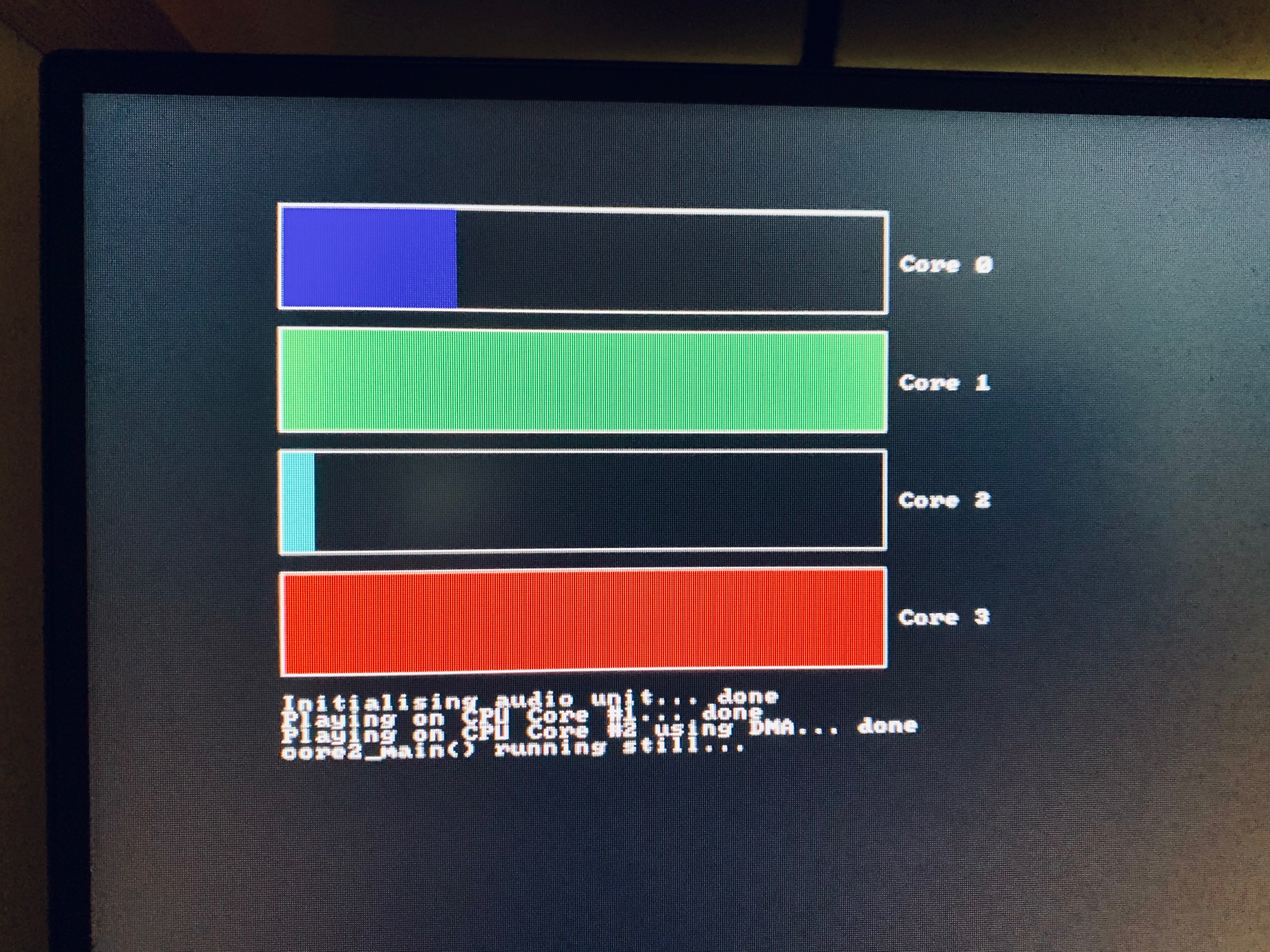
core0_main()- increments a progress bar every 1 second (roughly)core1_main()- has a two-step progress bar, playing an audio sample using the CPU at 50%, jumping straight to 100% when donecore2_main()- sets a DMA audio transfer, then increments a progress bar every half second (roughly), jumping to 100% as playback finishes- … and
core3_main()- increments a progress bar every quarter second (roughly)
main() is core 0’s entry point, which ultimately falls through to core0_main(), but not before it kicks off core3_main() and core1_main() by passing them to their respective start functions. When core1_main() finishes, it kicks off core2_main().
As you run this, you’ll see that these functions run in parallel on their respective cores. Welcome to symmetric multi-processing!
Coming up in part 11, we’ll put all of this work together for a multi-core version of our Breakout game.