Writing a “bare metal” operating system for Raspberry Pi 4 (Part 13)
What are interrupts?
If you’ve spent any time looking at the Bluetooth code in these tutorials, you’ll notice we’re always “polling” for updates. In fact, in part11-breakout-smp we tie up an entire core just waiting around for something to happen. This clearly isn’t the best use of CPU time. Fortunately, the world solved that problem for us years ago with interrupts.
Ideally, we want to tell a piece of hardware to do something and have it simply notify us when the work is complete so we can move on with our lives in the meantime. These notifications are known as interrupts because they disrupt normal program execution and force the CPU to immediately run an interrupt handler.
The simplest device that interrupts
One useful piece of built-in hardware is a system timer, which can be programmed to interrupt at regular intervals e.g. every second. You’ll need this if you want to schedule multiple processes to run on a single core e.g. using the principle of time slicing.
For now, however, we’re simply going to learn how to program the timer and respond to its interrupts.
The codebase
Let me quickly explain what you’re looking at in the part13-interrupts code:
- boot/ : the same boot code directory from part12-wgt
- include/ : some useful headers copied directly from part11-multicore
- lib/ : some useful libraries copied directly from part11-multicore
- kernel/ : the only new code we need to concern ourselves with in this tutorial
Please note: I have also done some work to tidy up the Makefile and respect this directory structure, but nothing to write home about!
The new code
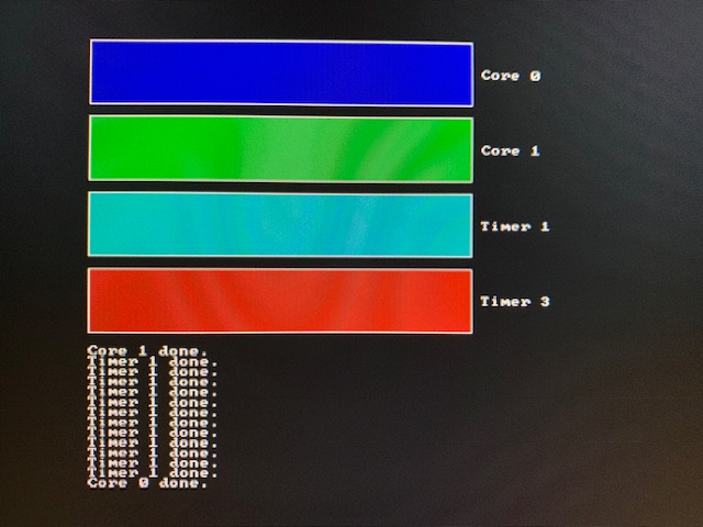
You’ll recognise a lot of kernel.c from part10-multicore, except instead of showing four cores at work and playing sound, we’re now only using core 0 & 1 and, in addition, making use of two timer interrupts to show four progress bars. So, the main() routine kicks off core 1, sets up the timers, and then finally kicks off core 0’s workload.
The timers are set up using these calls:
irq_init_vectors();
enable_interrupt_controller();
irq_barrier();
irq_enable();
timer_init();
Initialising the exception vector table
In fact, interrupts are a more specific kind of exception - something that, when “raised”, needs the immediate attention of the processor. A perfect example of when an exception might occur is when bad code tries to do something “impossible” e.g. divide by zero. The CPU needs to know how to respond when/if this happens i.e. jump to an address of some code to run which handles this exception gracefully e.g. by printing an error to the screen. These addresses are stored in an exception vector table.
irqentry.S sets up a list called vectors which contains individual vector entries. These vector entries are simply jump instructions to handler code.
The CPU is told where this exception vector table is stored during the irq_init_vectors() call from main() in kernel.c. You’ll find this code in utils.S:
irq_init_vectors:
    adr x0, vectors
    msr vbar_el1, x0
    ret
It simply sets the Vector Base Address Register to the address of the vectors list.
Interrupt handling
The only vector entry we really care about for the purposes of this tutorial is handle_el1_irq. This is a generic handler for any interrupt request (IRQ) that comes in at EL1 (kernel execution level).
If you do want a deeper understanding, I highly recommend reading s-matyukevich’s work here.
handle_el1_irq:
	kernel_entry
	bl      handle_irq
	kernel_exit
Put simply, kernel_entry saves the register state before the interrupt handler runs, and kernel_exit restores this register state before we return. As we’re interrupting normal program execution, we want to be sure that we put things back to how they were so that nothing unpredictable happens as our kernel code resumes.
In the middle we simply call a function called handle_irq() which is written in the C language in irq.c. Its purpose is to look more closely at the interrupt request, figure out what device was responsible for generating an interrupt, and run the right sub-handler:
void handle_irq() {
    unsigned int irq = REGS_IRQ->irq0_pending_0;

    while(irq & (SYS_TIMER_IRQ_1 | SYS_TIMER_IRQ_3)) {
        if (irq & SYS_TIMER_IRQ_1) {
            irq &= ~SYS_TIMER_IRQ_1;

            handle_timer_1();
        }

        if (irq & SYS_TIMER_IRQ_3) {
            irq &= ~SYS_TIMER_IRQ_3;

            handle_timer_3();
        }
    }
}
As you can see, we’re handling two different timer interrupts in this code. In fact, handle_timer_1() and handle_timer_3() are implemented in kernel.c and serve to demonstrate that the timer has fired by incrementing a progress counter and updating a graphical representation of its value. Timer 3 is configured to progress at 4 times the speed of Timer 1.
The interrupt controller
The interrupt controller is the hardware responsible for telling the CPU about interrupts as they occur. We can use the interrupt controller to act as a gatekeeper and allow/block (or enable/disable) interrupts. We can also use it to figure out which device generated the interrupt, as we did in handle_irq().
In enable_interrupt_controller(), called from main() in kernel.c, we allow the Timer 1 and Timer 3 interrupts through and in disable_interrupt_controller() we block all interrupts:
void enable_interrupt_controller() {
    REGS_IRQ->irq0_enable_0 = SYS_TIMER_IRQ_1 | SYS_TIMER_IRQ_3;
}

void disable_interrupt_controller() {
    REGS_IRQ->irq0_enable_0 = 0;
}
Masking/unmasking interrupts
To begin receiving interrupts, we need to take one more step: unmasking all types of interrupts.
Masking is a technique used by the CPU to prevent a particular piece of code from being stopped in its tracks by an interrupt. It’s used to protect important code that must complete. Imagine what would happen if our kernel_entry code (that saves register state) was interrupted halfway through! In this case, the register state would be overwritten and lost. This is why the CPU automatically masks all interrupts when an exception handler is executed.
The irq_enable and irq_disable functions in utils.S are responsible for masking and unmasking interrupts.
They are helped by the irq_barrier function which ensures that the enable_interrupt_controller() call properly finishes before the irq_enable() call is made:
.globl irq_enable
irq_enable:
    msr daifclr, #2
    ret

.globl irq_disable
irq_disable:
    msr daifset, #2
    ret

.globl irq_barrier
irq_barrier:
    dsb sy
    ret
As soon as irq_enable() is called from main() in kernel.c, the timer handler is run when the timer interrupt fires. Well, sort of…!
Initialising the system timer
We still need to initialise the timer.
The RPi4’s system timer couldn’t be simpler. It has a counter which increases by 1 with each clock tick. It then has 4 interrupt lines (0 & 2 reserved for the GPU, 1 & 3 used by us in this tutorial!) with 4 corresponding compare registers. When the value of the counter becomes equal to a value in one of the compare registers, the corresponding interrupt is fired.
So before we receive any timer interrupts, we must also set the right compare registers to have a non-zero value. The timer_init() function (called from main() in kernel.c) gets the current timer value, adds the timer interval and sets the compare register to that total, so when the right number of clock ticks pass, the interrupt fires. It does this for both Timer 1 and Timer 3, setting Timer 3 to run 4 times as fast.
Handling the timer interrupts
This is the simplest bit.
We update the compare register so the next interrupt will be generated after the same interval again. Importantly we then acknowledge the interrupt by setting the right bit of the Control Status register.
Then we update the screen to show our progress!
And… hey presto! You’re handling two system timer interrupts like a pro!