Writing a “bare metal” operating system for Raspberry Pi 4 (Part 14)
< Go back to part13-interrupts
Bare metal Ethernet for under £10
It’s exciting to build your own OS, but until you give it the ability to communicate with the outside world, your possibilities are limited. Indeed, our simple Bluetooth comms got us up and running - but if we’re to do anything meaningful then we need proper networking.
In this tutorial, we’re going to connect to an external Ethernet controller (a network card, if you like) using the RPi4’s Serial Peripheral Interface (SPI).
Things you’ll need:
- An ENC28J60 Ethernet module - it cost me less than £6 and was worth every penny (n.b. code only tested on this exact model)
- Some female-to-female jumper cables - cost me less than £2.50
- An Ethernet cable to connect to your Internet router
Connecting up the ENC28J60 Ethernet module
I followed the very helpful instructions here to hook up the ENC28J60 to the RPi4’s SPI0 interface.
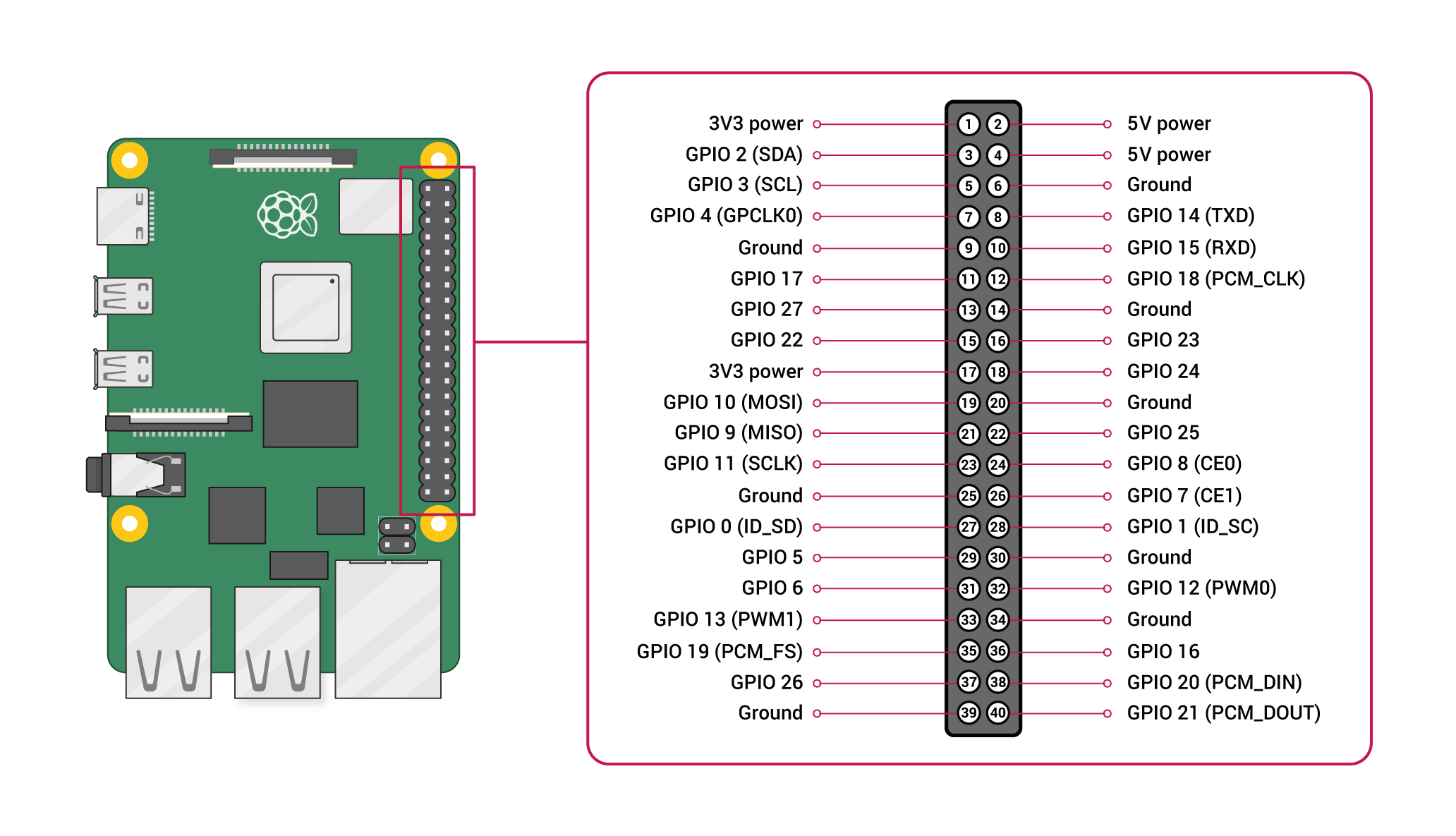
We won’t be connecting the interrupt line for now, so there are just six jumper leads (I’ve suggested colours) that need connecting:
| Pi pin | Pi GPIO | Jumper colour | ENC28J60 pin |
|---|---|---|---|
| Pin 17 | +3V3 power | Red | VCC |
| Pin 19 | GPIO10/MOSI | Green | SI |
| Pin 20 | GND | Black | GND |
| Pin 21 | GPIO09/MISO | Yellow | SO |
| Pin 23 | GPIO11/SCLK | Blue | SCK |
| Pin 24 | GPIO08/CE0 | Green | CS |
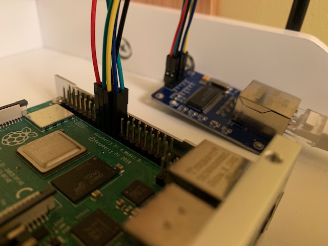
Here’s a (not very useful) photo of my RPi4 connected correctly:
The SPI library
Let’s start by looking at how we implement SPI communication.
I’m not going to write a long paper on how SPI works and why we need it, because it’s very well documented elsewhere. It’s recommended background reading, but not essential if all you want to do is get something working.
Look at lib/spi.c. It uses some of existing functions in lib/io.c that you’ll remember from earlier tutorials. In fact, I’ve added two functions to the include/io.h header file so we can call them from our SPI library:
void gpio_setPinOutputBool(unsigned int pin_number, unsigned int onOrOff);
void gpio_initOutputPinWithPullNone(unsigned int pin_number);
Specifically, spi_init() sets GPIO 7, 9, 10, and 11 to use the ALT0 function. Cross-referencing with the BCM2711 ARM Peripherals document, page 77, you’ll see that this maps SPI0 to the GPIO header. GPIO 8 is mapped as an output pin, since we’ll use this to signal to the ENC28J60 that we want to talk. In fact, the spi_chip_select() function takes a true/false (boolean) parameter which either sets or clears this pin.
Looking at the SPI0 register map on page 136, we see this reflected in our REGS_SPI0 structure. This gives us handy access to the SPI0 peripheral’s memory-mapped registers.
Our spi_send_recv() function then sets us up for some communcation:
- Sets the DLEN Register to the number of bytes to transfer (a length we passed into the function)
- Clears the RX & TX FIFOs
- Sets the Transfer Active (TA) flag
Then, whilst there’s either data to write or data to read (and we haven’t written/read more bytes than we asked for), we write to/read from the FIFO using the buffers we passed in. Once we think we’re done, we wait until the SPI interface agrees i.e. the DONE flag in the CS Register is set. If there are extraneous bytes to read, we just throw them away (well, dump them to the screen for now because this shouldn’t happen).
Finally, to be absolutely sure, we clear the TA flag.
I’ve then set up two convenient functions - spi_send() and spi_recv() - which exercise spi_send_recv(), mainly to make future code more readable.
The ENC28J60 drivers
Let’s now look into the net/ subdirectory.
Both enc28j60.c and enc28j60.h make up the driver code for the ENC28J60 Ethernet module. Whilst we could have laboured for months writing our own driver based on the module’s datasheet, I chose to leverage somebody else’s hard work instead. It felt like a win that I could effortlessly bring somebody else’s good code into my own OS! I did, however, make sure I understood what the code was doing at every turn (optional!).
Thanks to this Github repository for saving me months of work. I made a very few changes to the code, but nothing worth documenting here. If you’re keen to see how little I needed to change, clone the repo and make good use of the diff command.
What I did need to do is write some bridging code between the driver and the RPi4 hardware. Essentially, I’m talking about hooking up our SPI library to the driver - the whole reason for encspi.c.
It defines four functions that the driver requires (well documented in the enc28j60.h file):
void ENC_SPI_Select(unsigned char truefalse) {
    spi_chip_select(!truefalse); // If it's true, select 0 (the ENC), if false, select 1 (i.e. deselect the ENC)
}

void ENC_SPI_SendBuf(unsigned char *master2slave, unsigned char *slave2master, unsigned short bufferSize) {
    spi_chip_select(0);
    spi_send_recv(master2slave, slave2master, bufferSize);
    spi_chip_select(1); // De-select the ENC
}

void ENC_SPI_Send(unsigned char command) {
    spi_chip_select(0);
    spi_send(&command, 1);
    spi_chip_select(1); // De-select the ENC
}

void ENC_SPI_SendWithoutSelection(unsigned char command) {
    spi_send(&command, 1);
}
Perhaps the most confusing aspect is the chip selection. Through a bit of trial & error I discovered that when GPIO08 is clear, the device is selected, and when it’s set, the device is deselected. It turns out this is because the Chip Select pin on the ENC28J60 is active LOW and there’s no invertor on the board (presumably to save costs), so GPIO08 must be LOW to enable the IC.
Some more timer functions
The only other thing our ENC28J60 driver requires is access to a couple of well-defined timer functions:
HAL_GetTick()- returns the current number of timer ticks since startHAL_Delay()- delays by a specified number of milliseconds
These are quickly implemented in kernel/kernel.c and weren’t too much of a stretch after part13-interrupts:
unsigned long HAL_GetTick(void) {
    unsigned int hi = REGS_TIMER->counter_hi;
    unsigned int lo = REGS_TIMER->counter_lo;

    //double check hi value didn't change after setting it...
    if (hi != REGS_TIMER->counter_hi) {
        hi = REGS_TIMER->counter_hi;
        lo = REGS_TIMER->counter_lo;
    }

    return ((unsigned long)hi << 32) | lo;
}

void HAL_Delay(unsigned int ms) {
    unsigned long start = HAL_GetTick();

    while(HAL_GetTick() < start + (ms * 1000));
}
Let’s connect!
So we have a working driver that’s interfacing with our hardware via net/encspi.c and a few timer functions in kernel/kernel.c. Now what?
The design goals of our kernel’s networking demo will be to:
- Prove we can talk to the hardware
- Bring the network up successfully
- Prove we can connect to something else on the network and get a response
My proposals for how we fulfil these goals are:
- Prove we can detect whether a network link has been established at a physical level (CAT5 cable plugged in and connected to a working switch)
- Rely on the ENC28J60 driver to tell us that we’ve started up successfully
- Handcraft and send an ARP request and await an ARP response from my Internet router (the traditional way devices “find each other” on a network from a point of zero knowledge)
Look at kernel/arp.c. First we create a handle to reference our driver instance ENC_HandleTypeDef handle. We then initialise this structure in init_network():
handle.Init.DuplexMode = ETH_MODE_HALFDUPLEX;
handle.Init.MACAddr = myMAC;
handle.Init.ChecksumMode = ETH_CHECKSUM_BY_HARDWARE;
handle.Init.InterruptEnableBits = EIE_LINKIE | EIE_PKTIE;
This starts the module in half duplex mode (can’t transmit & receive simultaneously), sets its MAC address (my favourite: C0:FF:EE:C0:FF:EE), tells the hardware to add its own packet checksums (we don’t want to have to create them in software), and enables interrupt messages for “link up/down” and “packet received”.
We then call the driver routine ENC_Start(&handle) and check it returns true (this fulfils design requirement 2 - the driver tells us we’ve started correctly). We go on to set the MAC address using ENC_SetMacAddr(&handle).
This line waits until a physical network link has been established (fulfilling design requirement 1):
while (!(handle.LinkStatus & PHSTAT2_LSTAT)) ENC_IRQHandler(&handle);
The driver’s ENC_IRQHandler(&handle) routine would ordinarily be called when an interrupt was raised to refresh the driver status flags. Because we didn’t hook up the interrupt line and to keep things simple, we’re just polling in the software for now. When we see the handle.LinkStatus flag has the PHSTAT2_LSTAT bit set, we know the link is up (documented on page 24 of the module’s datasheet).
Before we’re done, we have to re-enable Ethernet interrupts (ENC_IRQHandler() disables them, but doesn’t re-enable them - something I discovered by reading the code).
Sending/receiving an ARP
To transmit on an Ethernet network, we need to format our packets correctly. The ENC28J60 deals with the physical layer (including the checksum, as we asked it to), so we only need concern ourselves with the data link layer - made up of a header, and a payload.
The header (our EtherNetII struct) is simply a destination and source MAC address, as well as a 16-bit packet type. ARP packets, for example, have type 0x0806. You’ll note in our #define ARPPACKET that we’ve swapped the two bytes. This is because big-endianness is the dominant ordering in network protocols, and the RPi4 is a little-endian architecture (some reading may be required here!). We’ve had to do this across the board.
The payload is the full ARP packet defined in the ARP struct. The SendArpPacket() function sets up the data we need in the structure (documented in code comments) and then uses driver calls to transmit the packet:
// Send the packet
if (ENC_RestoreTXBuffer(&handle, sizeof(ARP)) == 0) {
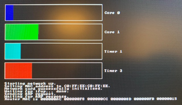
debugstr("Sending ARP request.");
debugcrlf();
ENC_WriteBuffer((unsigned char *)&arpPacket, sizeof(ARP));
handle.transmitLength = sizeof(ARP);
ENC_Transmit(&handle);
}
ENC_RestoreTXBuffer() simply prepares the transmit buffer and returns 0 if successful. ENC_WriteBuffer() sends the packet to the ENC28J60 over the SPI. We then set the transmit buffer length in the driver status flags and call ENC_Transmit() to tell the ENC to send the packet across the network.
You’ll see that the arp_test() function sends our first ARP this way. We tell it the IP of our router (192.168.0.1 in my case), but we don’t know its MAC address - that’s what we want to find out. Once the ARP is sent, arp_test() then waits for received Ethernet packets, checks whether they’re for us and, if they come from the router’s IP address (therefore likely to be the ARP response to our request), we print out the router’s MAC address.
This fulfils design requirement 3, and therefore we’re done! All we need to do is ensure that kernel/kernel.c calls our networking routines in the right order. I’ve chosen to do this on core 3 with a few easy-to-follow changes from where we left off in part13-interrupts. Essentially these are all the calls we need:
spi_init();
init_network();
arp_test();
Imagine how happy I was to see my router’s (correct!) MAC address appear on-screen - a sign of life, and proof that my OS is actually networking!