Writing a “bare metal” operating system for Raspberry Pi 4 (Part 3)
Making something happen
So far our OS doesn’t do a lot. So, how can we be sure that our code is actually running? Let’s do something more to really demonstrate that we have control of the hardware.
Usually, the first thing a software developer learns is to print “Hello world!” to the screen. In bare metal development however, printing to the screen can be quite a big challenge, so we’re going to do something simpler to start with.
Introducing the UART
Perhaps the easiest way we can “send a message” from our OS is via the UART or serial communications circuit. UART stands for Universal Asynchronous Receiver/Transmitter and it’s a very old and fairly simple interface that uses just two wires to communicate between two devices. Before USB came along, devices like mice, printers and modems were connected in this way.
We’re going to connect your dev machine directly to your RPi4 and have the RPi4 send the “Hello world!” message to your dev machine! Your dev machine will print it to the screen.
You will need:
- A USB to serial TTL cable
- To download and install drivers for the cable
- To download and install PuTTY on your dev machine
- If you’re using a Mac, I’d recommend installing Serial Tools as an alternative to PuTTY
If you’d like to read up on serial communcation before we start, I recommend looking at the SparkFun website.
Connecting the cable
If you have the drivers installed, go ahead and connect the cable to a spare USB port on your dev machine. Very little will happen, but if you now open Control Panel, click on Device Manager and open the Ports section, you should see a “Prolific” entry. That tells us that your cable is working correctly.
Here’s what my machine looks like:
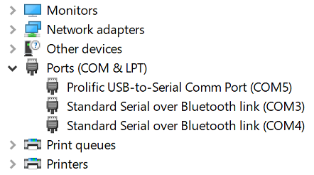
Make a note of the COMx number in brackets after the Prolific entry - in my case, that’s COM5.
The same cable will work on a Mac without the need to install any drivers.
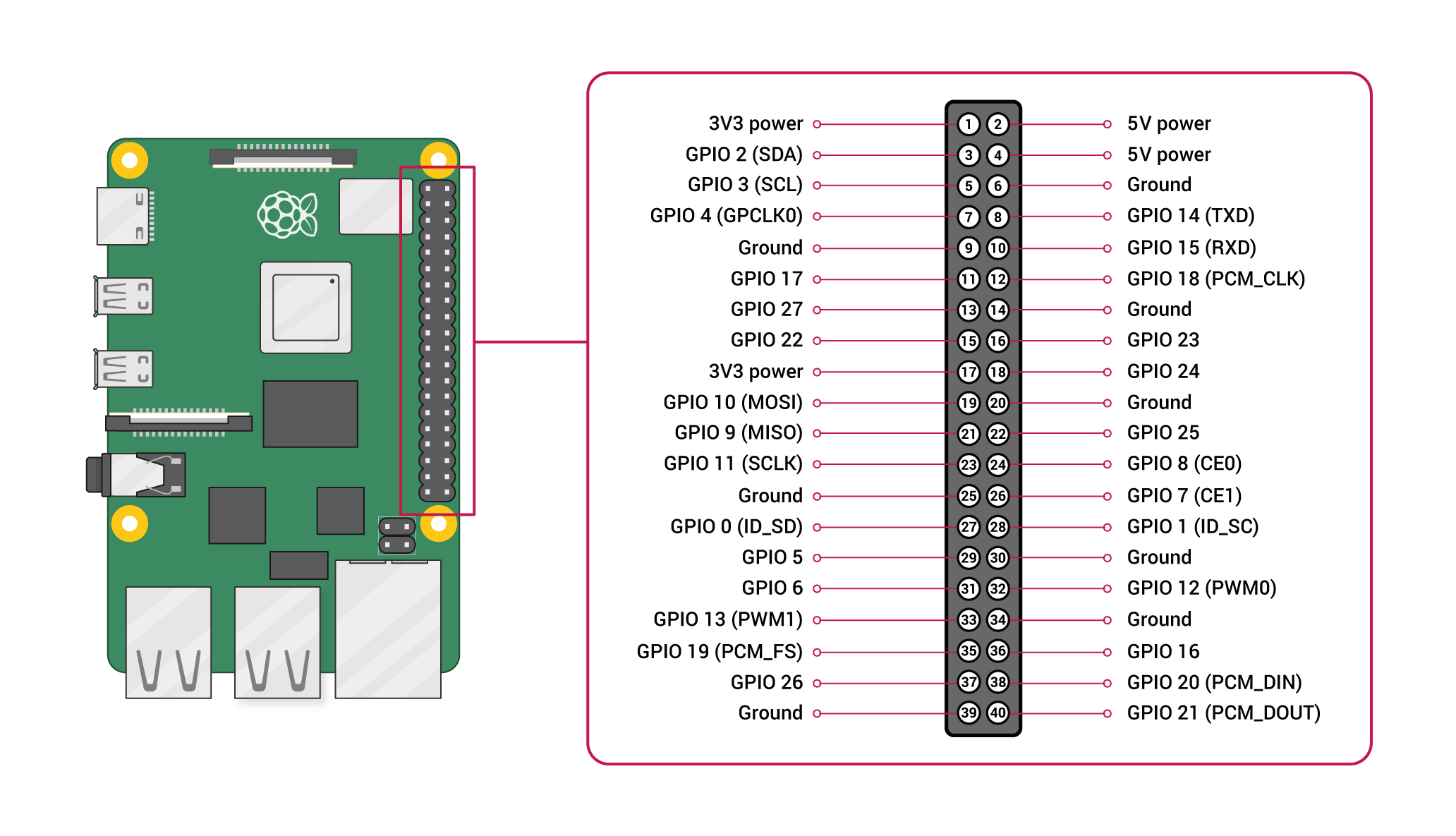
Now we need to look at the RPi4 to identify how to connect the other end of the cable. You’ll be looking for the GPIO pins, all 40 of them, which are just above the Raspberry Pi copyright notice.
The diagram below shows where you need to make connections. The cable I recommended has breakout leads that are colour-coded as follows:
- BLACK = Ground
- RED = +5v Power
- GREEN = TX (transmits from USB port to RPi4)
- WHITE = RX (receives to USB port from RPi4)
The Ground lead (BLACK in my case) hooks over the RPi4’s Ground pin (Pin 6), the RX lead (WHITE) over TXD (GPIO 14/Pin 8) and the TX lead (GREEN) over RXD (GPIO 15/Pin 10). Note how it’s necessary to cross RX and TX, i.e. connect RX to TX and vice versa. As we are powering the RPi4 using a dedicated power supply, make sure you don’t connect the RED connector.
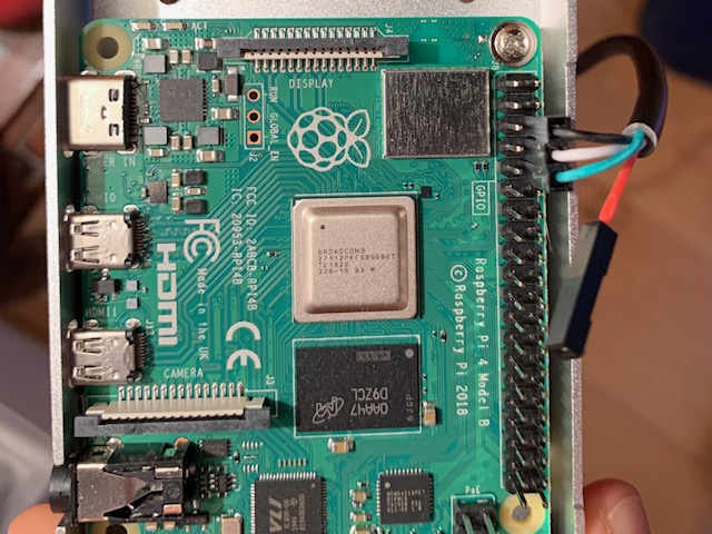
Here’s my RPi4 with the cable connected correctly:
Setting up PuTTY
- Run PuTTY on your dev machine
- Click on the “Session” category in the left-hand pane
- Set “Connection type” to Serial
- Click on “Serial” under the “Connection” category in the left-hand pane
- Set the “Serial line to connect to” to the COMx number we found above, mine was COM5
- Set the “Speed (baud)” to 115200
- Ensure “Data bits” is 8, “Stop bits” is 1, “Parity” is None and “Flow control” is None
- Click back to the “Session” category in the left-hand pane and you should see the changed settings
- Save these settings by typing a name e.g. “Raspberry Pi 4” in the textbox under “Saved Sessions” and clicking Save
- You can now start the connection by double-clicking on “Raspberry Pi 4” - if you do, all you will see for now is an empty black window
If you’re using a different terminal emulator, you’ll need to use the same settings as above following the application vendor’s instructions on how to use the software. For example, Serial Tools on Mac is explained here.
A quick config.txt change
Do you remember that, back in the first tutorial, I had to edit the config.txt file on the SD card to get Raspbian up on my TV screen? Now we need to add a line to ensure that our UART connection will be reliable.
UART communication is a lot to do with timing, and it’s important that both ends agree on the exact speed of data being sent/received. When we set up PuTTY, we told it to communicate at 115200 baud, and we’ll need the RPi4 to communicate at the same rate. As it is, we can’t be sure that it will - it might communicate faster or slower depending on how busy the CPU is.
Add this line to your config.txt to resolve this:
core_freq_min=500
Getting the UART going in code
First off, let’s update kernel.c to make a few new calls:
#include "io.h"

void main()
{
    uart_init();
    uart_writeText("Hello world!\n");
    while (1);
}
We start by including a new header file, io.h. This allows us to write some new code outside of the kernel.c file, and call it in when we need it.
You’ll note that our main() routine has also some new lines. First we call a function to initialise the UART, and then we call another function to write “Hello world!” to it. The weird character at the end of the string - \n - is how we add a newline to the end of our text, just like pressing Enter in a word processor!
Let’s now create io.h with the following contents:
void uart_init();
void uart_writeText(char *buffer);
This is a very short file with two function definitions. uart_init() is a void function with no parameters, just like main() is. This means that it doesn’t need any data from the caller to do its job, and it doesn’t send any data back to the caller when it’s done. You’ll note that uart_writeText is also a void function, but it does take a parameter since we need to tell it what text to write!
We’ll put the actual code for these functions in another new file, io.c:
// GPIO

enum {
    PERIPHERAL_BASE = 0xFE000000,
    GPFSEL0         = PERIPHERAL_BASE + 0x200000,
    GPSET0          = PERIPHERAL_BASE + 0x20001C,
    GPCLR0          = PERIPHERAL_BASE + 0x200028,
    GPPUPPDN0       = PERIPHERAL_BASE + 0x2000E4
};

enum {
    GPIO_MAX_PIN       = 53,
    GPIO_FUNCTION_ALT5 = 2,
};

enum {
    Pull_None = 0,
};

void mmio_write(long reg, unsigned int val) { *(volatile unsigned int *)reg = val; }
unsigned int mmio_read(long reg) { return *(volatile unsigned int *)reg; }

unsigned int gpio_call(unsigned int pin_number, unsigned int value, unsigned int base, unsigned int field_size, unsigned int field_max) {
    unsigned int field_mask = (1 << field_size) - 1;

    if (pin_number > field_max) return 0;
    if (value > field_mask) return 0;

    unsigned int num_fields = 32 / field_size;
    unsigned int reg = base + ((pin_number / num_fields) * 4);
    unsigned int shift = (pin_number % num_fields) * field_size;

    unsigned int curval = mmio_read(reg);
    curval &= ~(field_mask << shift);
    curval |= value << shift;
    mmio_write(reg, curval);

    return 1;
}

unsigned int gpio_set     (unsigned int pin_number, unsigned int value) { return gpio_call(pin_number, value, GPSET0, 1, GPIO_MAX_PIN); }
unsigned int gpio_clear   (unsigned int pin_number, unsigned int value) { return gpio_call(pin_number, value, GPCLR0, 1, GPIO_MAX_PIN); }
unsigned int gpio_pull    (unsigned int pin_number, unsigned int value) { return gpio_call(pin_number, value, GPPUPPDN0, 2, GPIO_MAX_PIN); }
unsigned int gpio_function(unsigned int pin_number, unsigned int value) { return gpio_call(pin_number, value, GPFSEL0, 3, GPIO_MAX_PIN); }

void gpio_useAsAlt5(unsigned int pin_number) {
    gpio_pull(pin_number, Pull_None);
    gpio_function(pin_number, GPIO_FUNCTION_ALT5);
}

// UART

enum {
    AUX_BASE        = PERIPHERAL_BASE + 0x215000,
    AUX_ENABLES     = AUX_BASE + 4,
    AUX_MU_IO_REG   = AUX_BASE + 64,
    AUX_MU_IER_REG  = AUX_BASE + 68,
    AUX_MU_IIR_REG  = AUX_BASE + 72,
    AUX_MU_LCR_REG  = AUX_BASE + 76,
    AUX_MU_MCR_REG  = AUX_BASE + 80,
    AUX_MU_LSR_REG  = AUX_BASE + 84,
    AUX_MU_CNTL_REG = AUX_BASE + 96,
    AUX_MU_BAUD_REG = AUX_BASE + 104,
    AUX_UART_CLOCK  = 500000000,
    UART_MAX_QUEUE  = 16 * 1024
};

#define AUX_MU_BAUD(baud) ((AUX_UART_CLOCK/(baud*8))-1)

void uart_init() {
    mmio_write(AUX_ENABLES, 1); //enable UART1
    mmio_write(AUX_MU_IER_REG, 0);
    mmio_write(AUX_MU_CNTL_REG, 0);
    mmio_write(AUX_MU_LCR_REG, 3); //8 bits
    mmio_write(AUX_MU_MCR_REG, 0);
    mmio_write(AUX_MU_IER_REG, 0);
    mmio_write(AUX_MU_IIR_REG, 0xC6); //disable interrupts
    mmio_write(AUX_MU_BAUD_REG, AUX_MU_BAUD(115200));
    gpio_useAsAlt5(14);
    gpio_useAsAlt5(15);
    mmio_write(AUX_MU_CNTL_REG, 3); //enable RX/TX
}

unsigned int uart_isWriteByteReady() { return mmio_read(AUX_MU_LSR_REG) & 0x20; }

void uart_writeByteBlockingActual(unsigned char ch) {
    while (!uart_isWriteByteReady());
    mmio_write(AUX_MU_IO_REG, (unsigned int)ch);
}

void uart_writeText(char *buffer) {
    while (*buffer) {
       if (*buffer == '\n') uart_writeByteBlockingActual('\r');
       uart_writeByteBlockingActual(*buffer++);
    }
}
You’ll see that the two functions we defined in our io.h header file now have some actual code, along with some other supporting functions. I’ll explain what’s going on in this code in the next tutorial, but let’s skip straight to the action now!
With your new io.c and io.h files in place, as well as the changes to kernel.c made, run make to build your new OS.
Then:
- Copy the newly built kernel8.img to the SD card, and then put the SD card into your RPi4
- Make sure your USB to serial TTL cable is connected correctly
- Run your terminal emulator (e.g. PuTTY) and connect to the “Raspberry Pi 4” session you set up earlier - you should see an empty black screen and no errors
- Power on your RPi4
If you’ve followed all these instructions, after a few seconds you’ll see “Hello world!” appear in the terminal emulator window on your dev machine.
It’s a message from your RPi4 to say that your OS is working. Proof at last!